Electronics
The electronics used for this project involve following:
1. Motors
Brushless DC motors which come with the Romi kit are used to drive the robot. They are small and low power but have a gear reduction of 120:1.
Further details about the motors can be found here.
2. Encoders
Encoders that are compatible with the Romi power board and the motors were purchased from this link.
3. Romi Power Board
Comes with the Romi kit.
4. STM32 Microcontroller
The STM32 NUCLEO-L476RG which was provided is the main microcontroller used for this project.
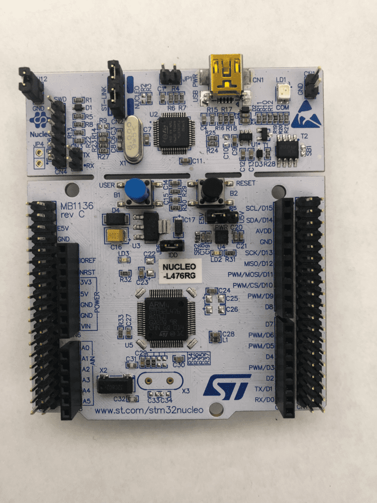
The following links are useful to learn about the Nucleo and identify the relevant pins:
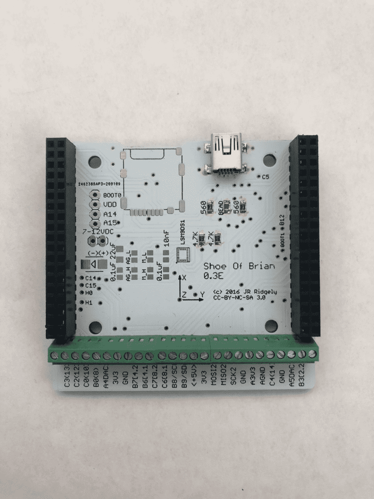
5. Shoe of Brian
The shoe of brian is a board custom designed by Dr. JR Ridgely that interfaces with the STM32 and translates micropython code to C which can be read by the STM32.
6. Reflectance sensors
In order to track the line, which is a 2 inch wide black strip on white paper, reflectance sensors were used.
This is of 6 channels with 8 mm spaced emitters with analog output from pololu. This was chosen after careful consideration of the line width and sensor separation. In this case, the sensor channels from which we collect data are 1,3,5,7,9,11. The even channels provide a weighted average of two neighbouring sensors which we did not have a need for. In a perfect orientation, 5 and 7 lie within the line and the rest are outside the line. This was the basis for the line tracking and error correction logic. Specifially in this case, an analog sensor works better than its digital counterpart to be able to finely distinguish the edge of the line.
7. Switch
Two switches/bump sensors are mounted at the front of the robot in order to detect any obstacles.
8. Inertial Measurement Unit (IMU)
A BNO055 IMU is mounted at the front part of the chassis. Its capable of nine degrees of freedom via an accelerometer, a gyroscope, and a magnetometer. It is used to track the position of the robot in order to avoid obstacles and retrace the track. A full manufacturer datasheet can be found on this link.
9. Batteries
The robot is powered by six AA rechargeable batteries which can run approximately 5 hours on a single charge.
10. Pin Connections
The following table summarizes the all the pins used on the STM32.
| Component | Signal | STM Header | STM Pin | Component Pin |
|---|---|---|---|---|
| Romi Board | PWR | CN7 | PWR | PWR |
| GND | CN7 | GND | GND | |
| Right Motor | PWM | CN10 | PC8 | PWM |
| Direction | CN10 | PC9 | DIR | |
| Enable | CN10 | PC7 | SLP | |
| Left Motor | PWM | CN10 | PB8 | PWM |
| Direction | CN10 | PB9 | DIR | |
| Enable | CN7 | PB7 | SLP | |
| Right Encoder | Channel 1 | CN10 | PA8 | ERA |
| Channel 2 | CN10 | PA9 | ERB | |
| Left Encoder | Channel 1 | CN10 | PB4 | ELA |
| Channel 2 | CN10 | PB5 | ELB | |
| Reflectance Sensor | Sensor 1 | CN7 | PC2 | S1 |
| Sensor 3 | CN8 | PA6 | S3 | |
| Sensor 5 | CN8 | PA7 | S5 | |
| Sensor 7 | CN10 | PA1 | S7 | |
| Sensor 9 | CN10 | PA0 | S9 | |
| Sensor 11 | CN7 | PC3 | S11 | |
| VCC | CN6 | 5V | VCC | |
| GND | CN6 | GND | GND | |
| Right Switch | VCC | CN6 | 5V | NO |
| GND | CN6 | GND | NC | |
| CTRL | CN5 | PB6 | C | |
| Left Switch | VCC | CN6 | 5V | NO |
| GND | CN6 | GND | NC | |
| CTRL | CN9 | PB10 | C | |
| IMU | PWR | CN7 | 5V | Vin |
| GND | CN7 | GND | GND | |
| SDA | CN7 | PA4 | SDA | |
| SCL | CN7 | PA5 | SCL | |
| Reset | CN10 | PB2 | RST |